
How it works
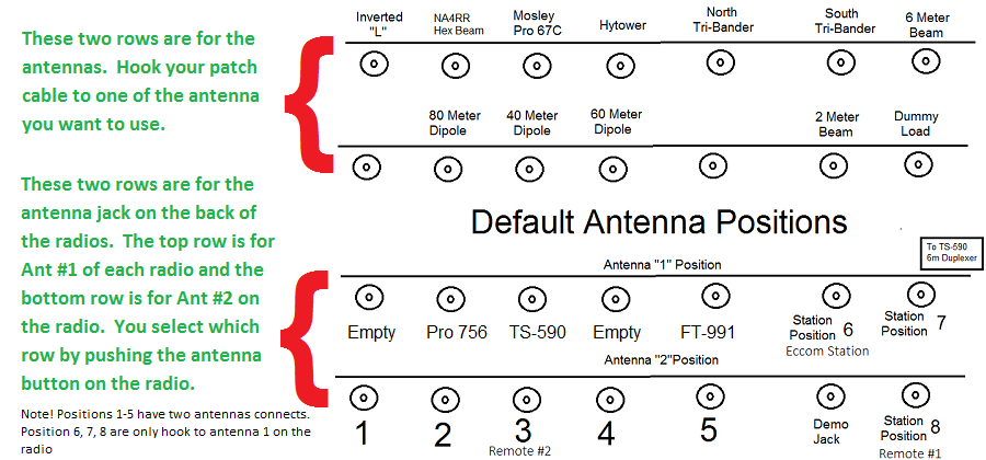
The panel has four rows. The top two rows are antennas and the bottom two rows are radios, each position labeled Pos 1, Pos 2, Pos 3 and so on. A radio’s position on the panel matches where it sits in the room.
For radio positions 1 through 5 there are two rows of jacks. Most HF radios have a front-panel button to select ANTENNA 1 or ANTENNA 2. The top row of jacks goes to the radio’s ANTENNA 1 connector and the second row to ANTENNA 2, so you can have two antennas patched to one radio and switch between them from the radio.
Radio positions 6, 7 and 8 have a single coax run. Leave those radios set to ANTENNA 1.
Protect the radios
Once everything is hooked up, always listen before you transmit. If you are not hearing anything, double-check your connections before keying up.
When you are done
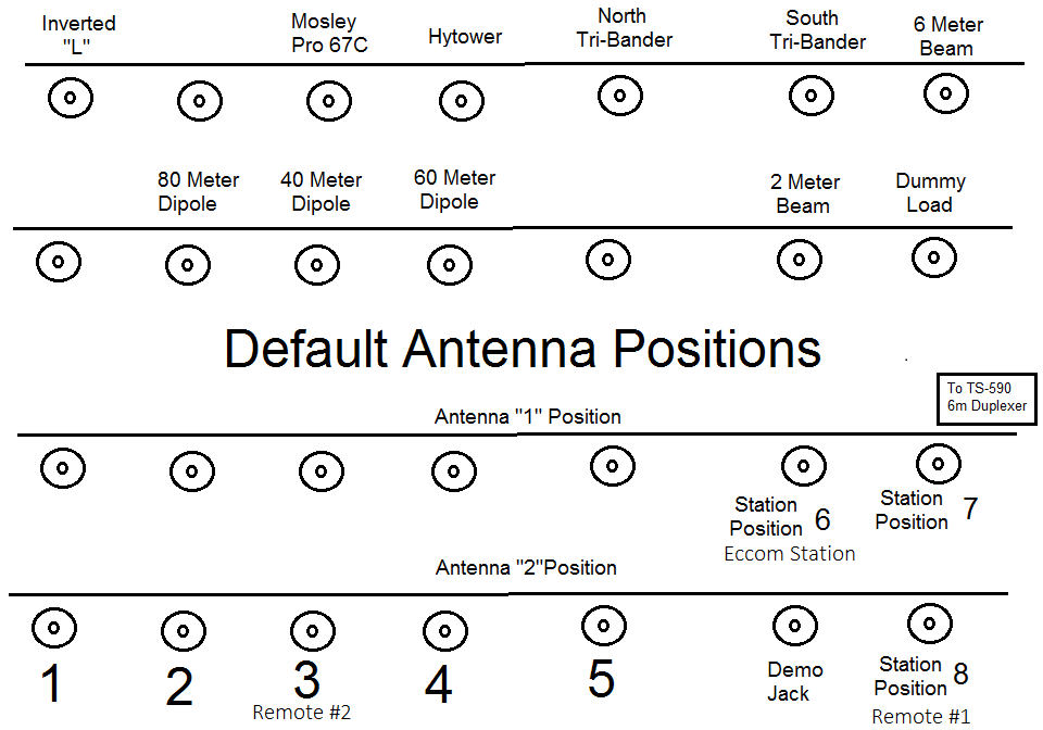
Local users always get to use whatever radio and antenna they want, so change the panel however you need. When you finish, please return the panel to the standard configuration below. The remote stations depend on it: if a remote is left unhooked or patched differently, it will not work, and someone from the technical committee has to drive up the hill to fix it.
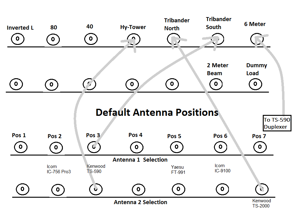
A blank panel diagram (PNG) is available if you want to sketch a setup.
Thank you. The technical committee.